
Gas Supply Collection
"Ensuring a Reliable Gas Supply: A Seamless Network of Pipelines" With the help of advanced technology and skilled professionals


All Professionally Made to Order for Quick Shipping
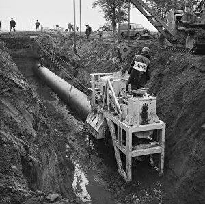
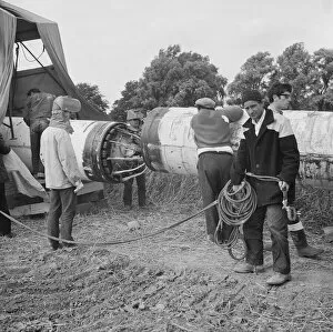
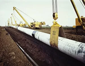
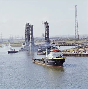
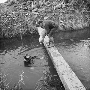
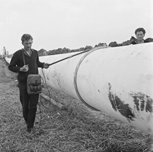
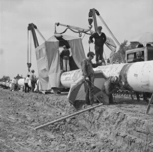
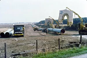
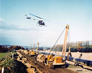
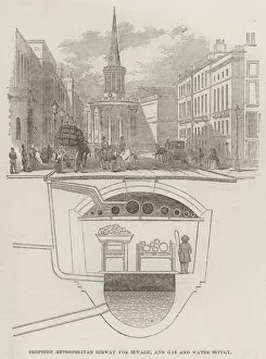
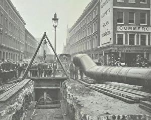
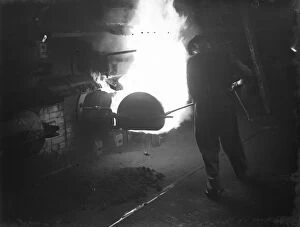
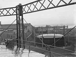
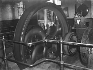
"Ensuring a Reliable Gas Supply: A Seamless Network of Pipelines" With the help of advanced technology and skilled professionals, the gas supply industry works tirelessly to ensure a seamless network of pipelines. From the initial stages of pipeline construction to maintenance and fault detection, every step is crucial in providing uninterrupted gas supply to homes and industries. The process begins with pipelaying operations like those captured in images such as "Pipelaying JLP01_08_077164" and "Pipelaying JLP01_08_076891. " Highly trained divers, as seen in "Diver JLP01_08_077160, " play a vital role in inspecting underwater sections for potential issues or damages. Thrust boring techniques showcased in "Thrust boring JLP01_08_077158" enable pipelines to pass beneath obstacles without disturbing the surrounding environment. Welders, depicted in "Welding JLP01_08_076889, " skillfully join sections together, ensuring structural integrity. To maintain safety standards, regular inspections are conducted using specialized equipment like the fault detector shown in "Fault detector JLP01_08_076822. " Any identified faults are promptly addressed through wrapping and sealing methods demonstrated by experts in "Wrapping and sealing JLP01-8-076816. " Once completed, these meticulously constructed gas pipelines such as those displayed under references like "Gas pipeline JLP01-8-076813" become an integral part of our infrastructure. They connect various regions efficiently while allowing for reliable distribution across vast distances. Even during periods when demand fluctuates or maintenance work is required, efficient management strategies come into play. Pipeline parking areas highlighted by images such as "Pipeline parking JLP0I-8-76835B" provide temporary storage solutions that facilitate necessary repairs or upgrades without disrupting supply chains. Behind every flickering flame on your stove or warm glow from your heater lies a complex network of pipelines.